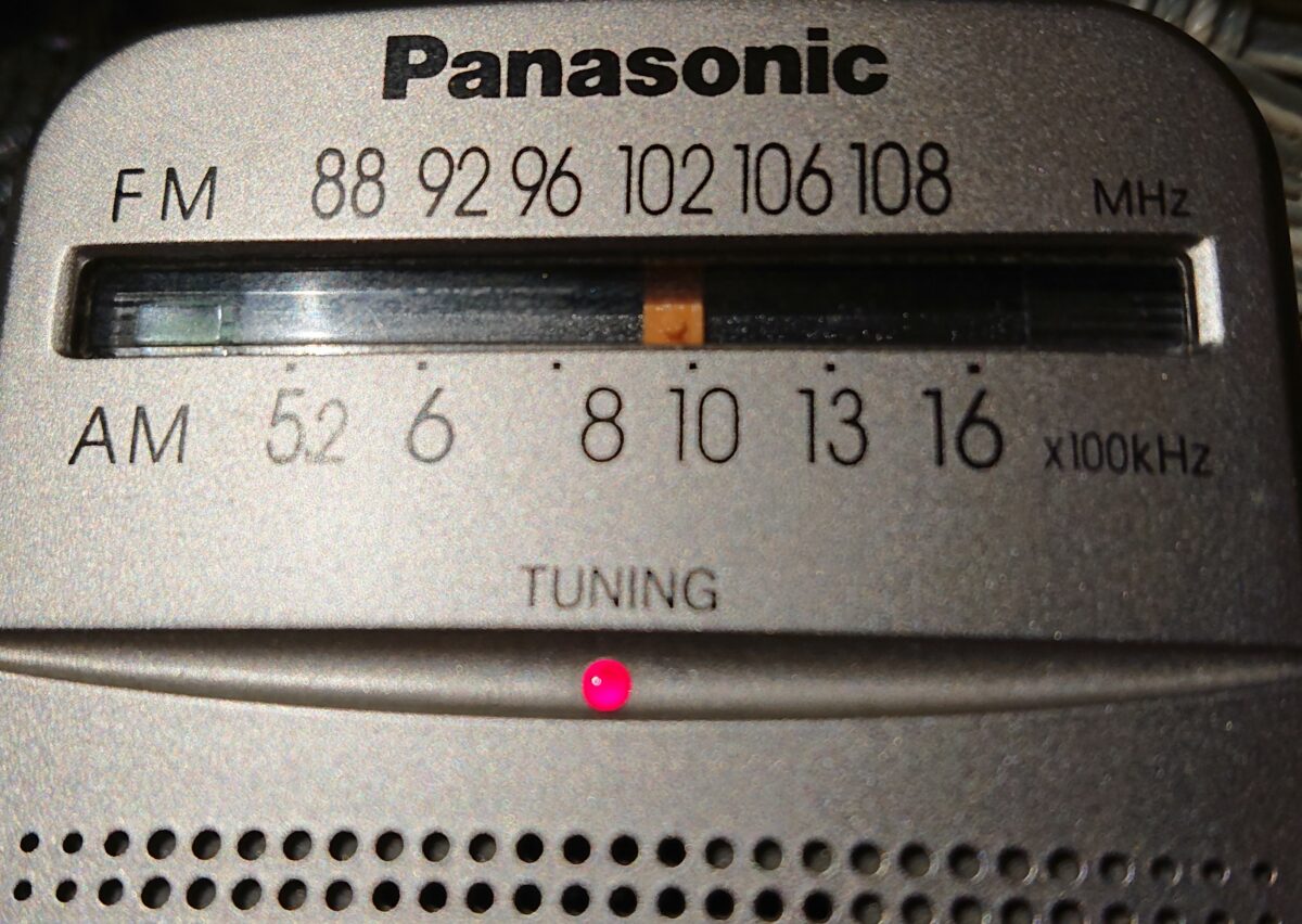
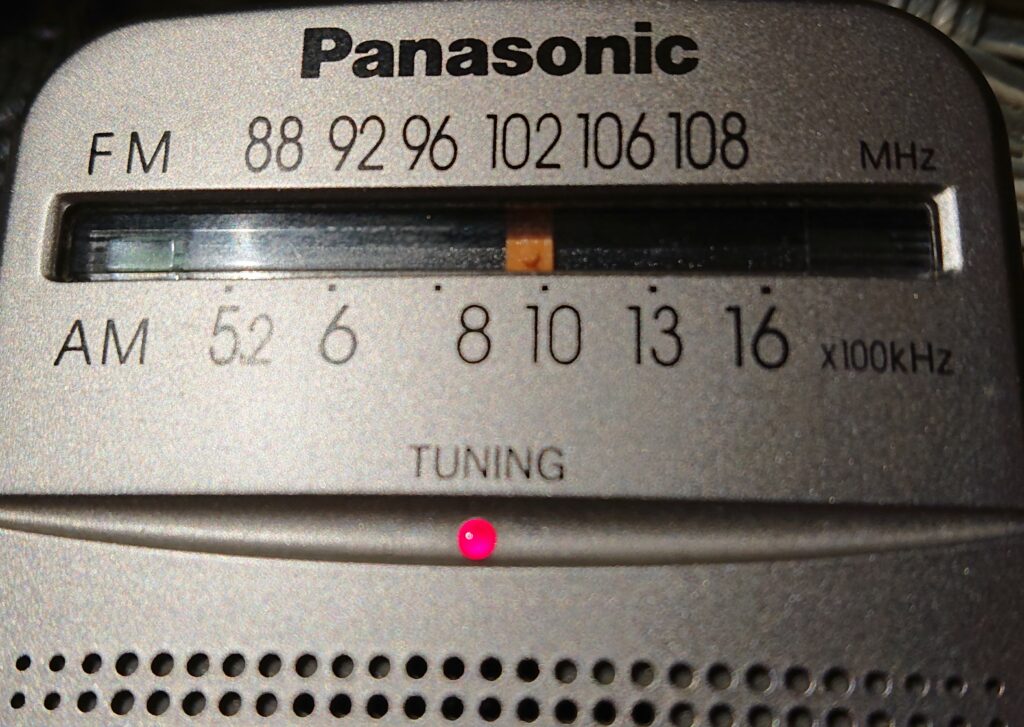
The Panasonic RF-P50 is a small portable/pocket AM/FM radio, with telescopic antenna and a bar antenna inside. It has somehow good sensitivity and selectivity on AM, also tuning is very precise and smooth. Beware: there is RF-P50D (with D at the end) version of the radio, but it’s the DSP version of it. Does not tune smoothly, and the RX is not as good as it can be in analog mode.
What can be done?
Assuming we want to use it for AM-DX, you can change the 455kHz IF-filter to a narrower one (not really needed, but I did), add one resistor to get the receiver to a much hotter state and re-align the full AM range to be very sensitive at all frequencies. As a bonus, you can change the mono (only left) headphone jacket to one for stereo headphones (without changing parts), although still in mono mode, but you will hear on both sides. To open the case, there is one screw in the battery containment and to loosen the board one screw at top right corner, near the bar antenna. There are also two plastic tabs on both board’s sides. Open the plastic housing and lift the board carefully to not break the tabs, like I did ;) Also pay attention to the switch and phones connector while lifting the back case side up.
Changing the IF-filter
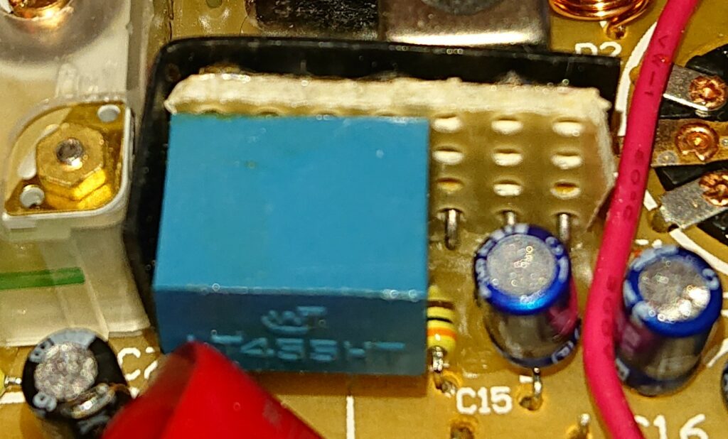
Allthough the internal filter is not that wide, you may want to change it, I used the LT455HT from my junk box. Changing it is straightforward, you may want to check if your filter needs any mechanical changes. I used a piece of universal printed board for it.
More gain and sensitivity
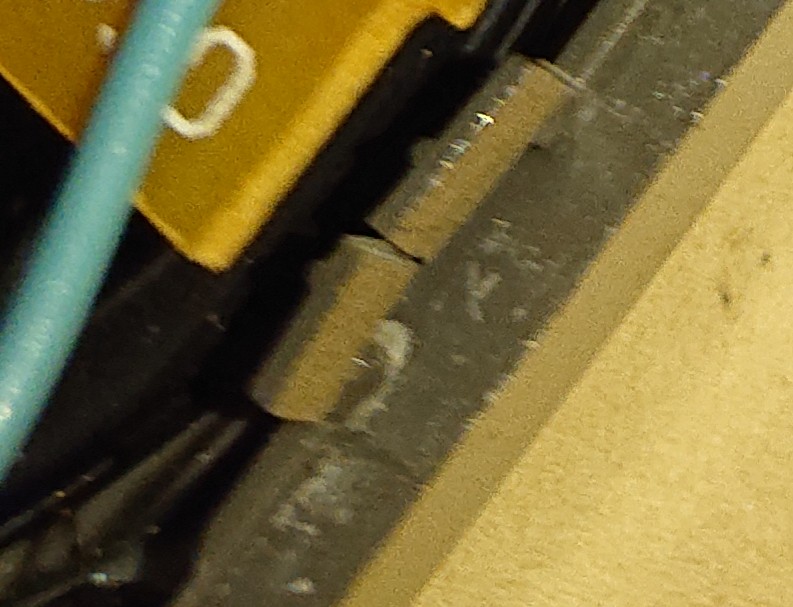
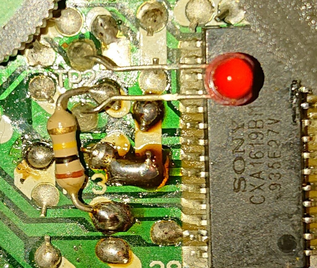
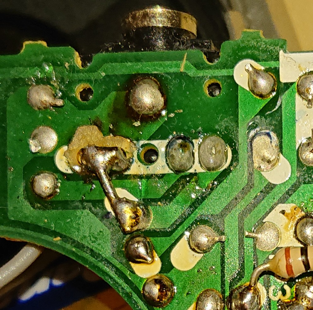
More gain can be added by soldering a small 100k resistor on the back side of the board between two points. It shifts the AGC curve (from what I understand). It works, in some way, like gamma correction for images. After change, realign T1 (black, near L5) for best IF center. No, the LED is not connected to the resistor as it may look on the picture.
Alignment procedure for AM
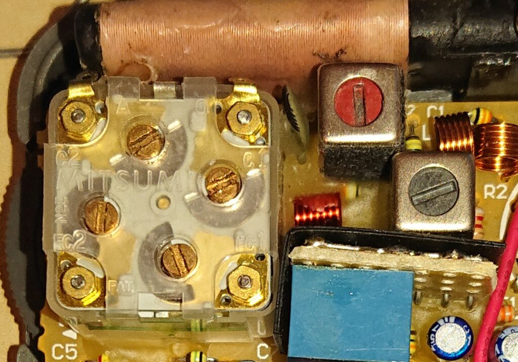
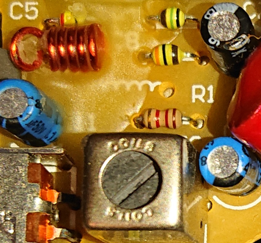
First set the radio to lowest frequency, C1 and C2 on VC1 (Mitsumi) to middle of range. Then align L5 (red) for best reception and best resonance on the lowest frequency. Then set the radio to highest freqency. Align C1 on VC1 for receiving on aproximately 1630 kHz and C2 on VC1 for best resonance on this frequency. Repeat, with every step more precise, until the radio does well on the whole scale, including the highest and lowest frequencies and the bar antenna is fully resonant. You may need to align T1 (black, near L5) to IF center for best reception.
Alignment for FM
FM is not what I use the radio for, but for your information, FC1 and FC2 on VC2 will do the job for FM as C1 and C2 do for AM. The small coil is for coarse frequency (squeeze or spread apart), T2 for base frequency and the C’s are for resonance and setting the highest frequency, as far as I can remember.
Both channels on stereo phones
The right channel is shorted to ground, it needs to be separated and connected to the left channel.
Additional works
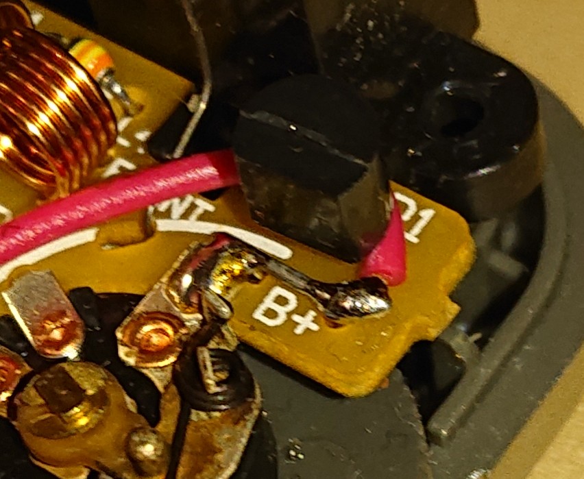
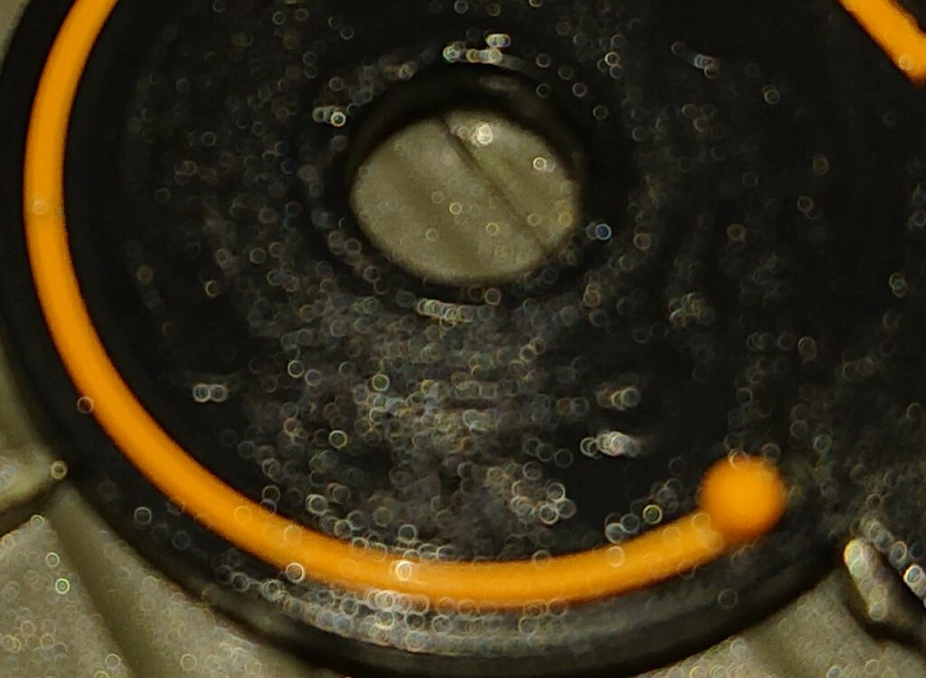
You may also shorten the diode to get more juice from your batteries (but then, please be careful with the polarization of the batteries). You could also lubricate the orange scale slider for smoother operation.
Last updated on 2025-04-02 at 23:15 UTC
Hello my friend; I am Sina from Iran; How beautiful this world is with people like you who guide people so honestly without any cost; I have benefited a lot from this guidance and prayed for you to always be successful and healthy. Thank you.